New ‘X-Series’ Digital Module


The latest upgrade to the Geochain HP, EHP and Slim downhole, high gain, low noise digitization modules. Each new X Series Digitizer has a 385°F (195°C) operating temperature which allows for operation in the most hostile well conditions.
ASL AS272 X Series 2018 Brochure AS272 X Series Digitizer Datasheet 251 (X series) Slim Digitizer Datasheet
Main Features:
- Upgraded Cooling system delivering 385°F (195°C) operating temperature
- Doubles System Data Rate- 60 tools at 1ms*
- Gapless Operation Option*
- Improved high temperature components, power supply and seals for increased robustness
- Integrated High Side indicator for tool roll and inclination
- Selectable damping and gain
- New ‘bypass’ function allows tools to relay data in the event of local power loss
- Facilitates ‘mix & match’ compatibility with GeochainSlim tools in the same string
- Compatible with Geochain and Geochain EHP
- GeochainSlim variant also available
*When used with X-Generation Telemetry Adapter and DFU.

Higher Temperature Operation
- The X-series digitizer upgrade for the Geochain/Slim/EHP system provides an improved 385°F (195°C) external operating temperature and higher telemetry rates. This allows continuous and longer term monitoring in the most hostile well conditions.
- This is the next development of the industry acclaimed AS271 low noise high gain digital module, which now introduces upgraded active cooling technology and thermal insulation components for increased robustness in addition to facilitating new operational functionality of your Geochain string.
The x-series digitizers AS-272 (ASR) and AS-251 (GSR) along with their equivalent X-(S)TAS telemetry adapter include:
- NEW 392°F (200°C) Rated Power Supply
- NEW 392°F (200°C) Rated D15 Connector Spring loaded mount for increased robustness
- NEW 500°F (260°C), 100 psi (internal) Hermetic Connector
- Upgraded Thermo-Electric Cooler with optimized heat exchange efficiency giving 385°F (195°C) External rating
- New Molecular Sieve to absorb airborne moisture
HSI High Side Indicator – XSeries
The new X-Series digitizer (AS272)* electronics have been recently implemented with a 3C solid state inclinometer system called a High Side Indicator (HSI), which measures the direction of the pull of gravity and calculates the angles of roll and vertical inclination in each shuttle of the Geochain toolstring.
HSI Orientation Guide PowerPoint
Main Features:
- Measures tool roll and inclination for every receiver for full 3-C geophone orientation
- Real time monitor read out and manual capture utility (along with internal electronics temperature)
- Automatic addition of HSI data to MIRF-6 header for each individual record
- The user can also manually capture the readout for all tools. (can be automatically correlated with WellTrack deviation listing in ACQ).
*When used with X-Generation Telemetry Adapter.
The new X-Series digitizer (AS272)* electronics have been recently implemented with a 3C solid state inclinometer system called a High Side Indicator (HSI), which measures the direction of the pull of gravity and calculates the angles of roll and vertical inclination in each shuttle of the GeochainTM toolstring.
The integrated system denotes tool inclination from vertical (DEV Angle 0-90°) and and clockwise roll looking downhole (Relative Bearing RB angle 1-359°).
Roll and inclination angles are determined from an accelerometer subsystem measuring the direction of the pull of gravity. If combined with a well deviation listing giving well azimuth trajectory (HAZI 1-359°), full 3-C processing can be achieve for all 3 components delivering a Vertical Up and Horizontal North/West field orientated dataset.
The current accuracy of the accelerometers tested for inclination measurement is ±0.1° with tool roll accuracy ±0.25° when positioned >9.9o from vertical.
The First rotation is that of the relative bearing (RB) angle, which is described in the plane orthogonal to the tool axis. RB is measure clockwise looking down from the vertical plane – borehole “high side” towards the direction of the arm opening Fig (a).

HSI Processing Steps for full 3C rotation

The integrated system denotes tool inclination from vertical and clockwise roll (looking downhole).
The example below shows the results comparing a raw correlated stack of a 3C near offset VSP dataset with that of a dataset with HSI roll values applied to the horizontal (X+Y) components.
A Full processing route guide for VSProwess will be released within the next Geochain User Manual. The HSI route guide v.1.3 can be downloaded here.
Please contact sales@avalonsciences.com for more detail.
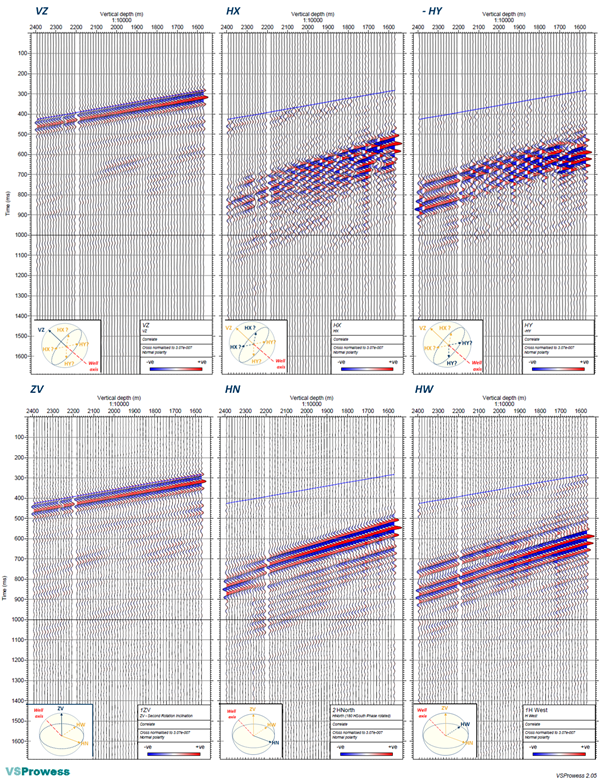
Top – Correlated raw common depth 3C stack plot in true amplitude, as recorded (no rotation applied). Bottom – After rotating the X,Y components with the highly erratic recorded HSI roll angle, showing a great coherency between adjacent depth levels.
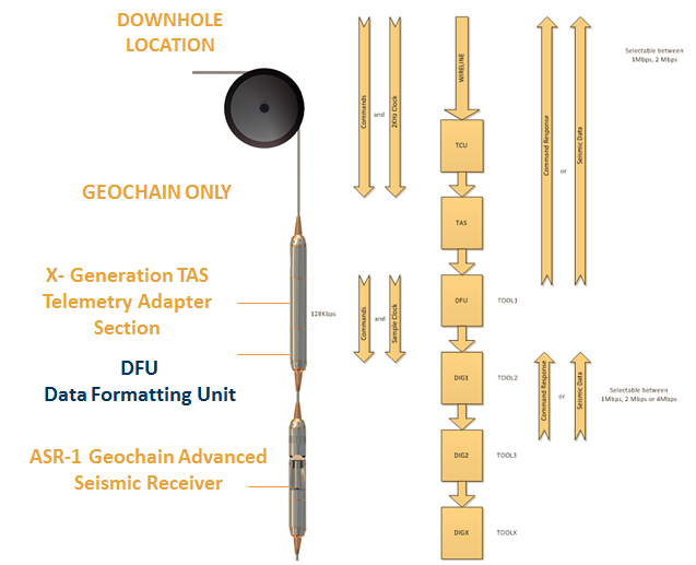
Data Formatting Unit
- The DFU is a downhole sonde that allows the user gapless operation when used with an X Generation TAS.
- It is located in between the X-TAS and the digitizers.
- Compatible with all Geochain digitizer modules for gapless recording
- Sim variant available (SDFU)
The DFU contains memory that stores digitizer data whilst the TAS has stopped, enabling the data to be continuous without gaps. The system shares the same x-generation unique Active Cooling System for continuous operation at 385oF/195oC and seals for 25,000psi (1700 bar) pressure rating
Extra Fucntionality if also using x-digitizers (AS-272 or AS-251)
- Facilitates both discrete buffering and formatted recording doubling the number of tools available for a given sample rate.
| DFU Specifications | |
| Length | DFU 9.75” (250 mm) From M-Rotating nut to Female end SDFU 33.7” (857mm) |
| Diameter | DFU 3” (76mm) SDFU 1 11/16” (43mm) |
| Weight | DFU 9.5 lb (4.3kg) SDFU 12.4 lb (5.7kg) |
| Temperature | 385oF/195oC (Digital Only) |
| Pressure | DFU 25,000psi (1700 bar) SDFU 20,000psi (1400 bar) |
| Panels | GMP or GPP & GSP-1 (Digital) |
| DFU Compatible* | Yes – Firmware upgrade required to all previous 2015 TAS-2/STAS Units |
| Wireline | 7 Conductor Heptacable |
Gapless Recording (Any digitizer)
Passive monitoring operations can often be long term. Discrete records result in a ~2 second gap between records. Over long monitoring periods this can potentially result in the missing of important seismic information. When acquiring ‘gapless’ records there is no delay between individual MIRF files.
This is available for all digitizers interfaced with an X-TAS and a DFU at the top of the string.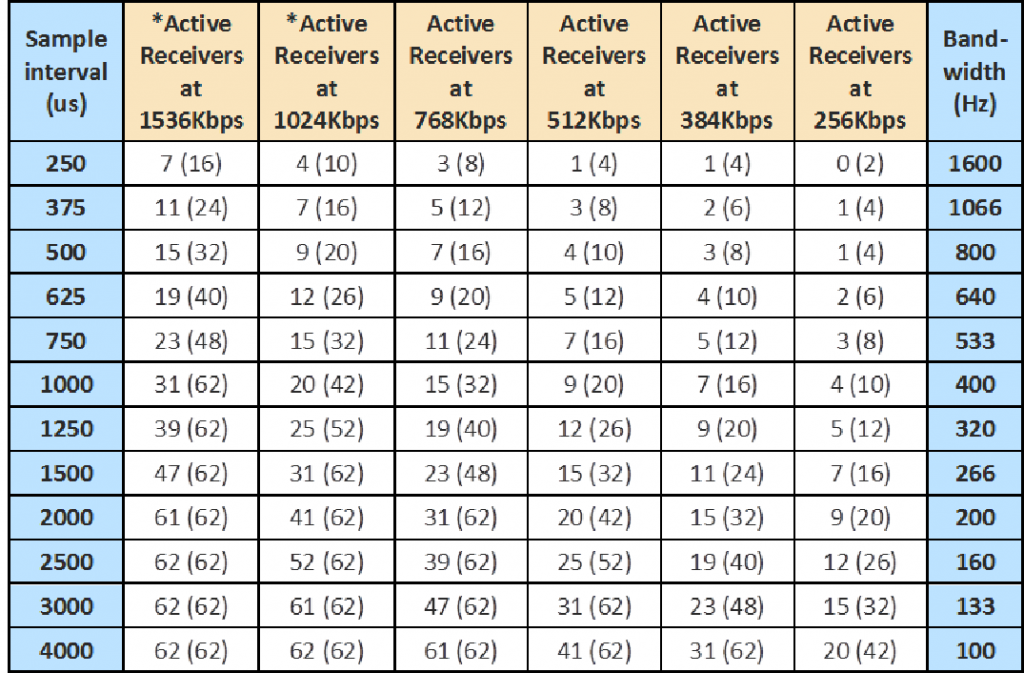
2016 Maximum active receivers—Gapless Recording (number in brackets = Formatted Gapless X-Series with DFU)
Formatted-Gapless Recording (X-Series Digitizers)
Formatted records are available when using complete X-Series electronics in combination with a DFU. Formatted operation allows an increase in the number of satellites available for a given tool sample rate (dictated by your tool data rate). ACQ will automatically detect and enable this function if you have the appropriate hardware.
- 16 Tools at 0.25 millisecond sample rate
- 62 Tools at 1 millisecond sample rate
- Gapless operation ideal for microcosmic recording
- Advanced error control and QC metrics
- Wireline quality
- Tool Quality
- ITC Quality
- Individual Tool Status
- Generates report files for ASL support team to preform advanced troubleshooting
Discrete Buffering (x-series only)
This is a new mode of operation only available to users with X-Series TAS, X-Digitisers and a DFU. This facilitates a buffering of the data to increase the amount of tools available when taking discrete records at a given data rate.
This mode surpasses the previous DBU functionality where recording durations are no longer simply doubled but rather only adds the time required to buffer the additional tools.

2016 Maximum active receivers—Discrete Recording (number in brackets = Discrete Buffered X-Series with DFU)
Discrete Record String Planning Utility
When configuring your downhole string using ACQ acquisition software you can now click on ‘String Planning’ to provide a pop up table to guide the user on the maximum amount of tools they could run for a given sample rate or data rate, in addition to providing a colour coded matrix indicating viable data rate/sample interval combinations for that number of receivers.

- Specify the number of tools in the top left box e.g. 30. Then Specify if error control is on/off
- Left side table shows maximum available tools for each Sample Interval/Data Rate. A green highlighted number means the system can accommodate the number of tools specified. A red number means you need to reduce your number of receivers to that level in order to record. You will notice more tools are available when using X-series electronics with DFU compared to standard digitizers (facilitated by the downhole buffering).
- The right hand matrix indicates the available sample interval and data rate combinations for the number of receivers specified. Red cells mean recording is unavailable with Green cells meaning recording is available. Grey Cells mean recording is available for those data rate/sample interval combinations but are limited to less than the 120s discrete record length. The available max record length is therefore described in the grey cell as a red number
Bypass Mode
Bypass Mode allows a tool with a faulty digitizer to be potentially bypassed.
Bypass = A ‘Bypassed’ Tool does not record or transmit data but allows receivers above and below the faulty tool to continue to supply data.
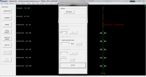
A Tool that has shown to go in to Bypass in ACQ will be identified on the Tool Display in the ‘Monitor’ menu as shown below
The original by-pass functionality, provided by AS-250s and AS-273s, allows data to pass through them once they lose power. This will only happen as a result of a hardware fault.
These tools can come in and out of by-pass continually with an intermittent fault.
New X-Generation digitizers (AS251s & AS272’s) have the standard bypass along with ‘enhanced’ hardware by-pass functionality. This means that if a module loses power and fails to be enumerated by the TAS then the string will continue to receive data from tools below.
The x-series digitizers will put themselves in by-pass mode if they are not enumerated by a TAS within 5 minutes of being powered up. They will do this under firmware control, without any inherent hardware fault.
Once by-passed they will stay by-passed forever, until commanded to reset themselves out of this mode (by Tool Reset).
ACQ 4.6 Match cable enumeration and cable lock process – allows for software handling of bypassed tools
By-pass mode is only supported by the following digitizers:
- ASR AS-273 Standard Bypass Only
- ASR-AS-272 Standard & Enhanced
- GSR-AS-250
- GSR-AS-251
Some major digitizer faults, such as a short circuit, trigger the X-series into ‘By-Pass’ mode. This allows the faulty digitiser to effectively disappear from the toolchain, but allow seismic data from tools below to pass through as if they were no longer present.
Once a cable has been locked ACQ will let you know if a tool goes missing from the toolchain. ACQ will then automatically compensate for the missing tool and assign seismic data to the correct channel.
ORDER THIS PRODUCT
CALL OUR SALES TEAM
+44 (0) 1458 270000